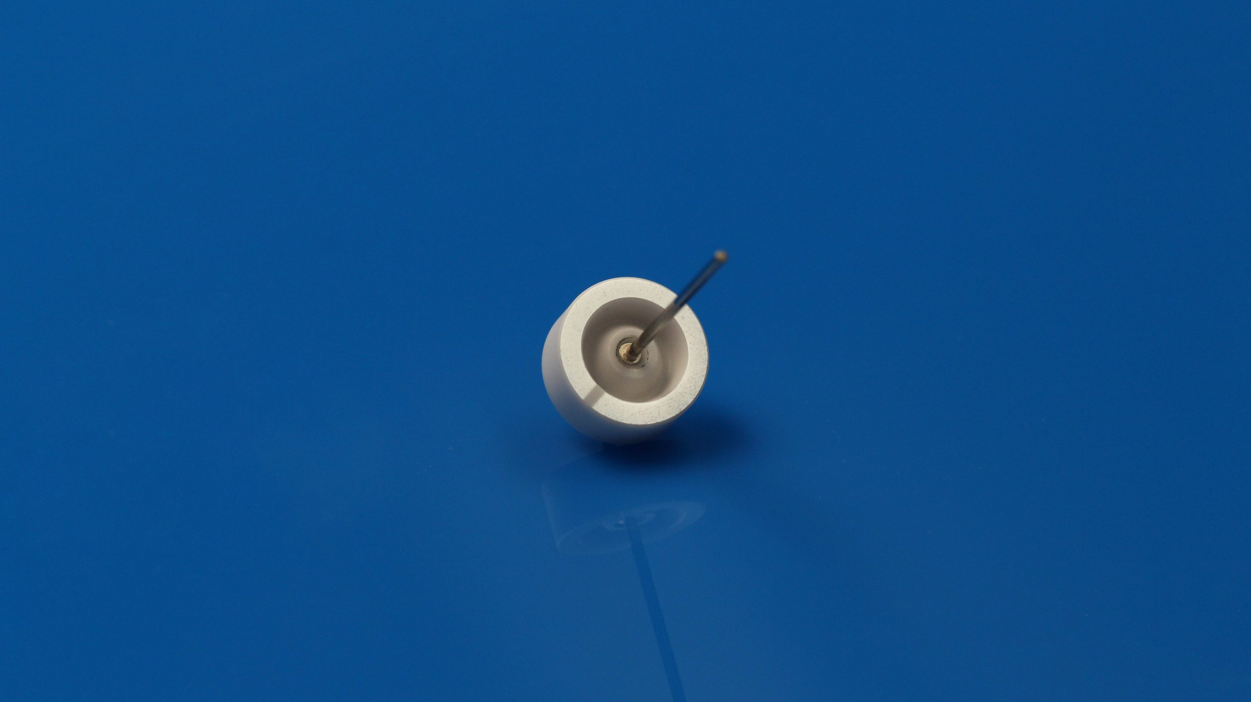
MPG400 Anode Assembly Replacement Case Study
How INNOVACERA developed a precision, non-OEM anode assembly from a customer-supplied reference component for vacuum gauge repair and refurbishment.
Important compatibility notice: The component described in this case was independently developed by INNOVACERA. It is not an OEM part and is not manufactured, authorized, endorsed or supplied by the original vacuum-gauge manufacturer. Compatibility must be confirmed against the actual gauge, sample, drawing and operating conditions.
Project at a Glance
| Application | Vacuum gauge repair and refurbishment |
|---|---|
| Reference equipment | MPG400 combined Pirani and inverted magnetron vacuum gauge |
| Component | Internal anode assembly |
| Development route | Customer-supplied reference component + dimensional review + drawing confirmation |
| Key engineering concerns | Electrode position, concentricity, ceramic insulation, assembly stability and cleanliness |
| Supply approach | Small-batch sample development followed by customer validation |
| Final validation | Gauge assembly, functional test and calibration by the customer / qualified service provider |

The Challenge
The MPG400 combines Pirani and inverted magnetron measuring principles. In the cold-cathode measuring section, the relationship between the internal electrodes, ceramic insulation and surrounding structure is important to correct installation and gauge operation.
The anode assembly is small, but it is not simply a turned metal rod. A usable replacement must control the features that affect installation, insulation and electrode positioning.
- Anode position relative to the surrounding structure
- Electrode straightness and assembly concentricity
- Ceramic-insulator dimensions and electrical separation
- Mechanical stability of the ceramic-to-metal structure
- Cleanliness of surfaces exposed to the vacuum environment
- Correct orientation and positioning during installation
Because the reference component had already been used in service, it could not automatically be treated as a perfect dimensional master. Wear, contamination, bending and previous handling had to be considered before a controlled manufacturing drawing was established.
The MPG400 spare-parts documentation refers to this component as “anode, complete.” In this case study, we use anode assembly as the general engineering term.
Why a Customized Replacement Was Considered
| Original spare-part sourcing becomes difficult | A repair can remain open while waiting for the required internal component. |
|---|---|
| Only the anode assembly is damaged | Replacing the complete gauge or a larger repair set may not always be commercially necessary. |
| Available drawings are incomplete | A sample-based engineering review is needed before dimensions can be confirmed. |
| Only a small quantity is required | The project must support sample validation before repeat purchasing. |
| Fit and function depend on several interfaces | A visual copy alone is not enough to establish compatibility. |
| Final accuracy depends on the complete instrument | Component inspection cannot replace gauge-level functional testing and calibration. |
Engineering Approach
1. Review the Reference Component
We first reviewed the customer-supplied anode assembly and identified the dimensions and interfaces that could influence installation or operation. The review covered overall length, installation depth, ceramic-insulator dimensions, electrode diameter and straightness, assembly orientation, contact/support surfaces and visible signs of wear or contamination.
Where the used component could not provide sufficient certainty, dimensions were treated as values requiring customer confirmation rather than being copied automatically.
2. Identify Critical-to-Function Characteristics
| Characteristic | Why it matters | Control approach |
|---|---|---|
| Anode position | Affects the electrode relationship inside the measuring chamber | Controlled against a defined drawing datum |
| Electrode straightness | Reduces installation misalignment risk | Dimensional / visual inspection |
| Assembly concentricity | Supports repeatable positioning | Fixture-assisted measurement |
| Ceramic dimensions | Affect insulation distance and mechanical fit | Precision dimensional inspection |
| Joint stability & cleanliness | Supports handling stability and reduces avoidable contamination | Process control, cleaning and protected packaging |
3. Confirm Materials and Insulation Requirements
The ceramic section must provide electrical insulation while maintaining dimensional stability during handling, assembly and service. Alumina is commonly considered for this type of component because of its high electrical resistivity, mechanical strength, dimensional stability and established precision-processing capability.
Material purity, metal grade, surface treatment, joining method, cleaning requirement and any electrical test criteria should still be confirmed for the specific project rather than assumed from the gauge model alone.
4. Confirm the Drawing Before Manufacturing
The measurable requirements were converted into a controlled drawing for customer review. The drawing defined critical dimensions and tolerances, materials, assembly direction, inspection datums, surface/cleanliness requirements and any customer-specific test items.
For this type of repair component, photographs alone are not sufficient for a reliable compatibility decision. A physical sample, approved drawing or sufficiently complete dimensional information is normally required.
5. Manufacture and Assemble Under Controlled Handling
The ceramic and metallic elements were manufactured to the confirmed drawing, with attention to ceramic damage, electrode displacement and contamination after cleaning. Clean tools, controlled handling and protected packaging were treated as part of the process.
Component-Level Inspection
Because final measurement performance depends on the complete gauge, pre-shipment inspection focused on characteristics that can be verified at the component level.
| Inspection category | Typical item | Acceptance basis |
|---|---|---|
| Dimensions | Overall dimensions, ceramic dimensions, installation interfaces | Approved drawing |
| Position | Electrode alignment / concentricity | Defined datum and measurement method |
| Appearance | Cracks, chips, deformation, contamination | Agreed visual standard |
| Electrical | Insulation resistance / DC withstand test where specified | Agreed voltage, duration and acceptance criteria |
| Documentation & packaging | Required records, clean protected packing | Purchase-order / project requirements |
Project-Specific Technical Requirements
The following values were treated as project-specific acceptance items in the source case and should not be presented as universal specifications for every anode assembly.
| Parameter | Example project requirement | Qualification |
|---|---|---|
| Concentricity | ≤ 0.5 mm | Must reference a defined datum and measurement method |
| Insulation resistance | > 10⁹ Ω | Test voltage, environmental conditions and acceptance criteria must be defined. |
| DC withstand test | 2–4 kV DC | Test voltage, duration, leakage-current limit and acceptance criteria must be agreed before testing. |
Leak testing should only be specified when the component structure contains a relevant sealed boundary and when the test method and acceptance value are agreed in advance.
From Component Verification to Gauge-Level Validation
A replacement anode assembly cannot be validated independently from the gauge in which it operates. Dimensional conformity confirms the component against the approved project specification; it does not by itself prove the final measurement accuracy of the repaired instrument.
| Validation stage | Typical responsibility | Purpose |
|---|---|---|
| Incoming inspection | Customer / repair provider | Confirm dimensions and condition |
| Mechanical installation | Qualified service technician | Verify fit, orientation and electrode position |
| Electrical check | Repair provider | Confirm insulation and electrical connection |
| Vacuum-system test | Customer / calibration laboratory | Observe gauge response under controlled vacuum conditions |
| Calibration comparison | Qualified calibration provider | Compare the repaired gauge with a reference gauge |
Final gauge performance may also be affected by the Pirani element, chamber contamination, magnet and electrode condition, controller configuration, gas species, ignition behavior, installation orientation, cable/electronics condition and the calibration procedure.
Outcome
The project established a controlled development route for an MPG400 anode assembly based on the customer’s reference component and confirmed requirements.
- Project-specific dimensional review
- Identification of critical assembly and insulation features
- Controlled manufacturing drawing
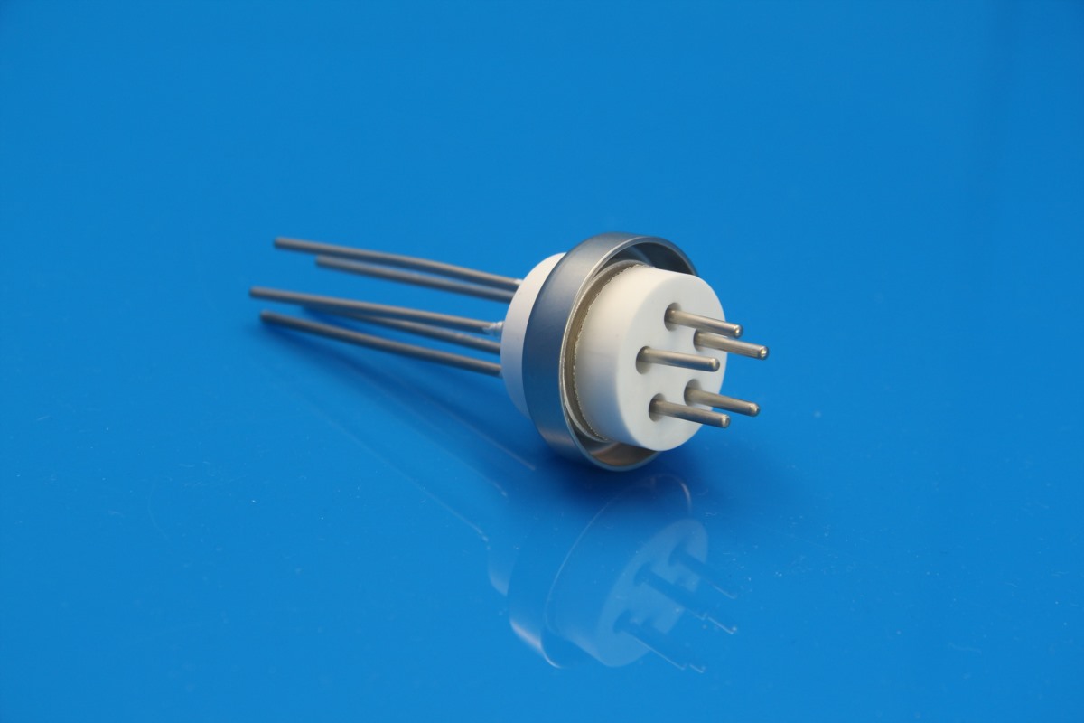
- Customized ceramic-and-metal anode assembly
- Component-level dimensional and visual inspection
- Sample verification before a larger purchasing decision
For the customer, the value was not simply another small component. The project provided a structured option for evaluating a non-OEM replacement when standard spare-part sourcing was difficult or commercially impractical. Final gauge performance remained subject to correct installation, the condition of the other gauge components and calibration of the complete instrument.
What Engineers Should Provide for a Similar Project
| Gauge model and configuration | Identifies the application and general interfaces |
|---|---|
| Original or used component sample | Supports dimensional and structural review |
| Existing drawing / critical dimensions | Reduces uncertainty in sample measurement |
| Required ceramic and metal materials | Supports material selection and process planning |
| Applied voltage and vacuum conditions | Supports insulation and application review |
| Gas / cleaning requirements | Supports contamination-control planning |
| Required inspection records | Defines documentation before production |
| Sample quantity and validation method | Defines the initial supply and approval route |
Frequently Asked Questions
What is the “anode, complete” in the MPG400 repair kit?
In the MPG400 spare-parts documentation, the complete anode component is listed as “anode, complete.” This corresponds to the anode assembly discussed in this case study. INNOVACERA supplies an independently developed non-OEM component rather than the complete OEM repair kit.
Is this an original OEM MPG400 part?
No. It is an independently developed, non-OEM component intended for repair, refurbishment and customized replacement projects.
Can it be treated as a universal plug-and-play replacement?
No. Compatibility must be evaluated against the specific gauge, reference component, drawing, dimensions and operating conditions.
Can development start from a used sample?
Yes, but a used part may be worn, bent or contaminated. Critical dimensions should be confirmed before manufacturing.
Does replacing the anode guarantee the original measurement accuracy?
No. Final performance depends on the complete gauge, installation, electronics, contamination, gas type and calibration.
Can electrical insulation be tested before shipment?
Yes, when the test voltage, duration, environmental conditions and acceptance criteria are defined in the project specification.
What information is needed for quotation?
Ideally: gauge model, sample or drawing, required quantity, critical dimensions, materials, applied voltage, vacuum conditions and required inspection documents.
Discuss Your Vacuum Gauge Repair Project
When an original spare part is unavailable, has a long lead time, or does not suit a customized repair program, INNOVACERA can evaluate a new component based on your sample, drawing and technical requirements.
- Photos of the existing component
- Gauge model and configuration
- Available drawing or dimensions
- Required quantity
- Operating voltage and vacuum conditions
- Known failure symptoms
- Required inspection or test reports
Non-OEM and Compatibility Statement
The component described in this case is independently developed and manufactured by INNOVACERA for vacuum gauge repair, refurbishment and customized replacement applications. It is not an OEM part and is not manufactured, authorized, endorsed or supplied by the original vacuum-gauge manufacturer.
Suitability for a specific instrument must be evaluated and verified from the customer’s sample, drawings, dimensions, materials and operating conditions. Third-party brand names, model numbers and equipment references are used solely for application identification and do not imply authorization, affiliation, partnership or endorsement.