.svg)
Function
The oxygen or lambda sensor in a properly functioning exhaust system monitors the A/F ratio, as often as one hundred times per second, and reports this information to the vehicle’s ECU or engine control unit (also referred to as the PCM or ECM). The proper adjustments are then made to ensure that this ratio is ideal or stoichiometric, helping the automobile burn fuel more efficiently. Most oxygen sensors use the core material of zirconia, which produces voltage in relation to the amount of oxygen in the exhaust.
Evolution
Oxygen sensors were developed by the Robert Bosch Company and first used on Volvo applications in the late 1970’s. Originally, automotive oxygen sensors had only one or two wires and were made from zirconia in a thimble shape. They relied upon the heat in the exhaust system to warm them to their required operating temperature. The problem associated with this concept was that it took a very long time for the sensors to go from nonoperational (thus leaving the ECU in open loop mode) to operational (which is necessary for closed loop mode), typically over a minute. Some automobile manufacturers purposely retarded ignition timing to heat the exhaust to afford faster oxygen sensor and catalyst warm up. When located close to the engine (a requirement to warm the sensors to the adequate operating temperature) it was not possible to monitor the exhaust gases from both engine banks – another downfall of early sensor designs.
In the early 1980’s, oxygen sensor manufacturers added a small rod type heater in the center of the thimble that warmed the ceramic thimble to its operating temperature much faster. The heated sensors could be mounted downstream next to the catalytic converter – a more desirable location because the exhaust gases were in a more homogenous state and the potential for sensor overheating was reduced dramatically. The first versions were three wire sensors that employed a case ground for the sensor signal. Later applications employed four wire versions with an isolated ground.
Starting in the early 1990’s for California vehicles & 1996 for the other 49 states, OBDII controls were implemented. The requirements of the oxygen sensor increased dramatically. New technologies were developed and sensors were placed in more locations, thus increasing their feedback to the ECU. The current narrow band sensors, which only allowed for readings of “rich” or “lean,” were replaced. The new generation of four and five wire wide band sensors are now being employed on many vehicle applications. These sensors allow for exact measurements of A/F ratio, allowing for true emission control.
While the first sensor equipped vehicles had a single sensor, today’s vehicles can have up to eight. The original one wire thimble sensor has been joined by heated, planar, titania, FLO (fast light off), UFLO (ultra-fast light off), wideband and A/F ratio sensors. The modern oxygen sensor, due to its sophistication and placement, is what allows for the fuel injected and low emission engines of the modern vehicle.
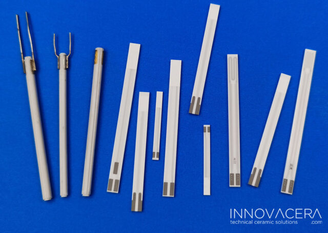
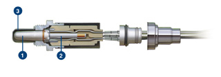
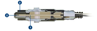
Typical Sensor Components
Thimble type
Planar type
Innovacera offer both thimble and planar type of oxygen sensor heaters, if you have more interesting, pls contact with us.
Declaration: This is an original article of INNOVACERA®. Please indicate the source link when reprinting: https://www.innovacera.com/news/a-brief-history-of-oxygen-sensors.html.


 Enquiry