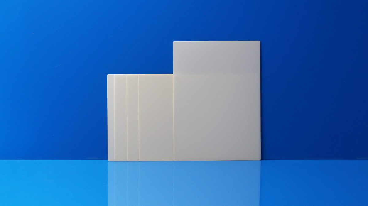
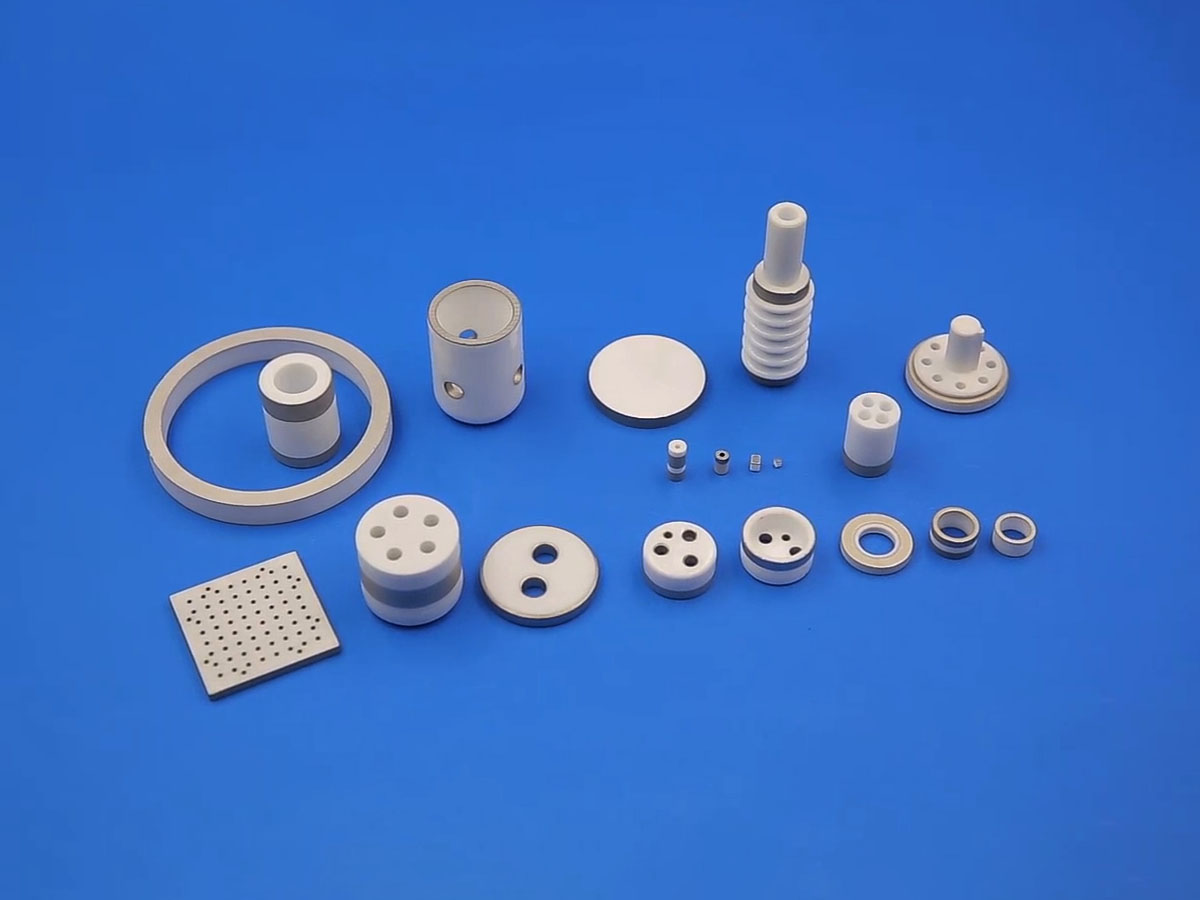
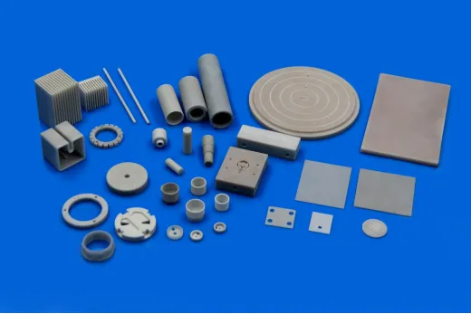
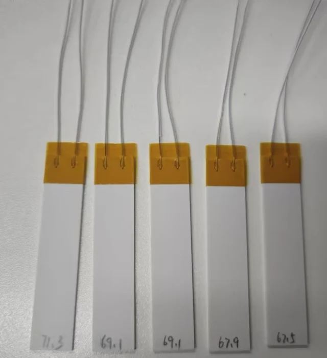
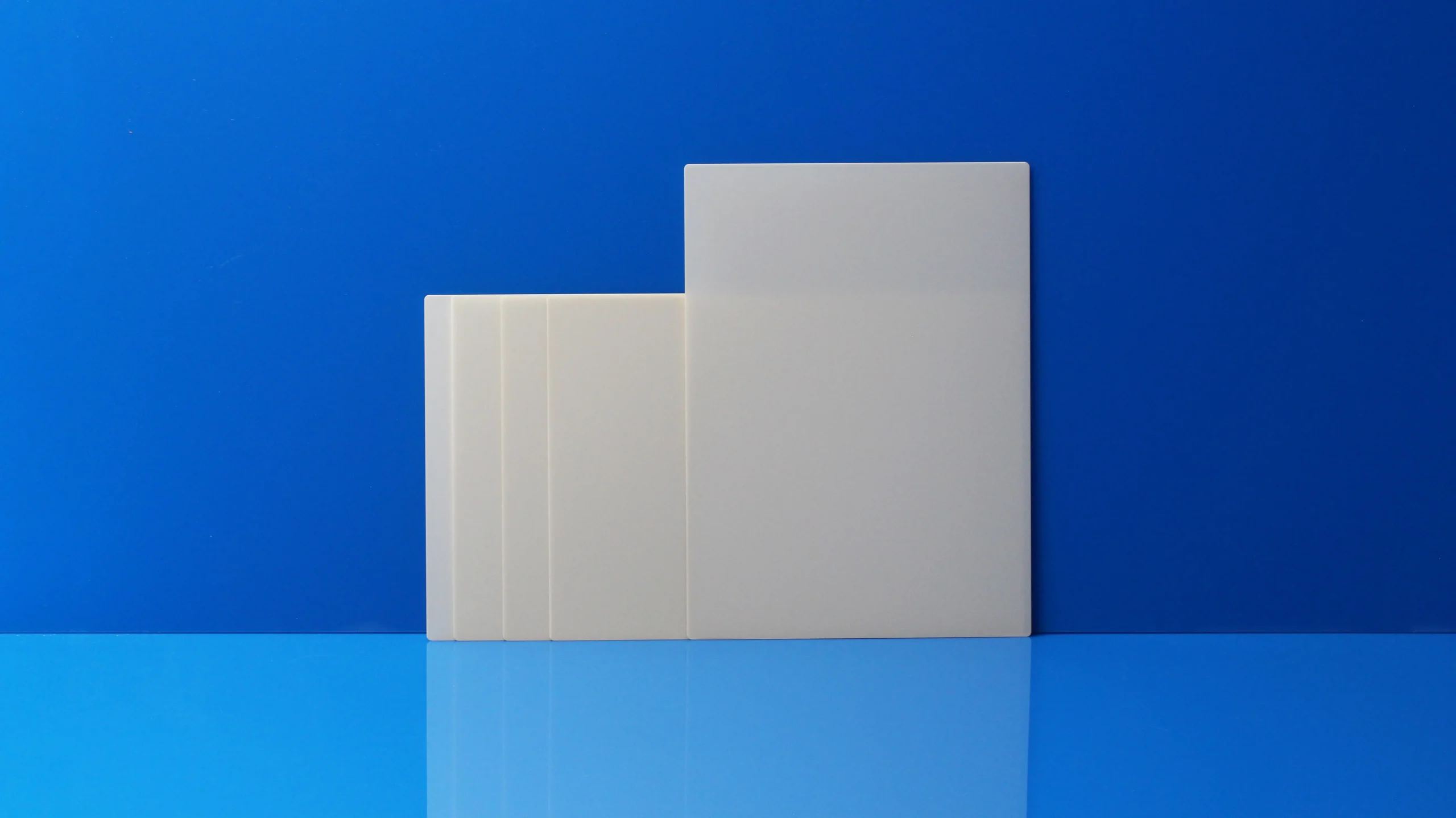
In thick-film resistors, power resistors, and power electronic modules, ceramic substrates provide structural support for the resistive film and act as the primary heat-transfer bridge. Standard alumina (Al₂O₃) works reliably for conventional low-to-medium power resistors due to its dependable dielectric isolation, mechanical rigidity, and cost-effectiveness.
However, as power densities rise and heat concentrates into smaller component footprints, substrate thermal conductivity becomes the decisive factor determining operating temperatures, resistance stability, and overall service life.
Engineers frequently select aluminum nitride (AlN) substrates instead of alumina for high-power thick-film designs. Yet AlN is not universally necessary for every application. Material selection hinges on resistor heat generation, heat flow paths, and the substrate’s specific thermal role within the entire assembly.
1. What Role Does the Ceramic Substrate Play in Thick-Film Resistors?
Thick-film resistors use a ceramic carrier upon which resistive pastes, conductor traces, and protective overglazes are screen-printed and fired. Beyond mechanically supporting these functional layers, the ceramic substrate forms the first and most critical link in the thermal conduction path:
Resistive film → Ceramic substrate → Thermal interface material (TIM) / Solder → Heat sink or PCB
During operation, the resistive element continuously dissipates electrical energy as heat. If the substrate’s bulk thermal resistance is high, heat cannot escape rapidly to downstream cooling layers, causing steep localized temperature rises (hot spots). For high-power density resistors, selecting a ceramic substrate with optimized thermal conductivity is a baseline prerequisite.
2. Why Is Alumina Still the Dominant Substrate for Standard Resistors?
96% alumina (Al₂O₃) substrates remain a standard choice across the resistor industry. It provides high volume resistivity, high dielectric breakdown strength, robust mechanical endurance, and predictable thermal behavior at an economical price point. Furthermore, thick-film resistor pastes and firing profiles have been optimized for alumina over decades.
For resistors operating under moderate power loads where temperature rise stays well within safe operating margins, alumina remains the most sensible choice. Replacing alumina with a higher-cost alternative is unnecessary unless heat dissipation reaches a design bottleneck.
Aluminum nitride is not meant to replace alumina across the board; rather, it provides a specialized solution when power density and thermal dissipation demands exceed alumina’s physical limits.
3. Why Is Aluminum Nitride Ideal for High-Power Resistors?
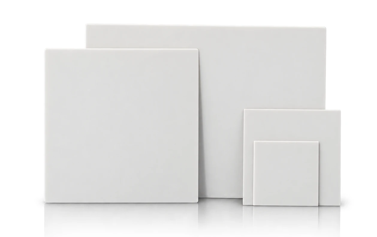
Aluminum nitride uniquely bridges two conflicting physical properties: high electrical insulation and exceptional thermal conductivity (170–230 W/m·K)—roughly 7 to 9 times higher than that of 96% alumina (approx. 24–26 W/m·K).
In high-power thick-film resistors, replacing alumina with AlN delivers immediate thermal advantages:
- Dramatic Thermal Resistance Reduction: Heat moves rapidly through the substrate cross-section, suppressing hot spots and reducing peak film temperatures.
- Silicon-Matched Thermal Expansion: AlN possesses a low coefficient of thermal expansion (CTE ≈ 4.5 × 10⁻⁶/K), closely matching silicon and common semiconductor alloys. This minimizes interfacial shear stress during high-frequency thermal cycling.
- Higher Power Handling per Unit Area: Devices can either handle higher wattages within existing form factors or achieve compact miniaturization without exceeding thermal budgets.
However, real-world thermal performance depends heavily on ceramic purity, grain boundary chemistry, and density. When specifying AlN, engineers should evaluate material grade, thermal conductivity ratings, thickness tolerances, flatness, and surface roughness.
4. When Should You Upgrade from Alumina to Aluminum Nitride?
The decision to migrate from alumina to aluminum nitride should be driven by thermal modeling and layout constraints rather than generic material preferences.
| Design Factor | Evaluate / Retain Alumina (Al₂O₃) | Upgrade to Aluminum Nitride (AlN) |
|---|---|---|
| Power Density | Temperature rise remains comfortably within specification | High wattage in a compact area causes unmanageable hot spots |
| Thermal Bottleneck | Substrate thermal resistance is negligible compared to system cooling | Ceramic layer contributes a major portion of total thermal resistance |
| Package Size | Enclosure allows ample area for convective cooling or larger traces | Miniaturization restricts PCB footprint and heatsink contact area |
| Cost Budget | Cost-sensitive commercial consumer applications | High-reliability, industrial, automotive, or RF power applications |
| Paste Compatibility | Standard commercial ruthenium oxide / thick-film pastes used | Pastes and firing profiles qualified specifically for AlN substrates |
If thermal simulations reveal that the alumina substrate accounts for a substantial fraction of total thermal resistance, upgrading to AlN directly eliminates the primary bottleneck. Conversely, if the bottleneck lies in the thermal interface grease or an undersized heatsink, upgrading the substrate material alone yields diminishing returns.
5. Thermal Paths in High-Power SMD and Current-Sense Resistors
As power supplies, motor drives, and EV battery management systems demand higher power in smaller surface-mount packages (e.g., 2512, 1206 power chips), thermal management within the resistor component becomes crucial.
In SMD resistors, heat flows from the resistive trace through the ceramic substrate, across the solder joints, and into the PCB copper planes. In these compact layouts, heat cannot spread laterally without encountering high resistance. A high-conductivity AlN substrate allows heat to spread quickly across the entire bottom and termination zones, reducing thermal resistance to the board.
Engineers must assess the complete thermal chain: Resistive film → Ceramic substrate → Solder / Termination → PCB copper pads → Heatsink. Selecting the correct substrate material requires balancing each thermal resistance element along this path.
6. Beyond Thermal Conductivity: Critical Parameters for AlN Resistor Substrates
Thermal conductivity is only one of several essential specifications when selecting aluminum nitride for thick-film resistors:
- Substrate Thickness: Thinner substrates shorten the thermal conduction distance, but must retain sufficient mechanical strength during automated assembly and handling.
- Surface Roughness (Ra): Standard as-fired AlN substrates usually feature Ra values around 0.4–0.6 μm. For ultra-fine pitch printing or thin-film resistors, precision lapping and polishing (Ra < 0.05 μm) may be required.
- Camber and Flatness: Strict camber control (typically < 0.3%) ensures uniform screen printing, consistent paste thickness, and void-free soldering or bonding to heatsinks.
- Paste System Compatibility: AlN has different surface chemistry and thermal expansion behavior than alumina. Pastes formulated for alumina cannot be transferred to AlN without verifying adhesion, TCR (temperature coefficient of resistance), and firing furnace atmospheres.
- Batch Consistency: High-volume automated production demands lot-to-lot consistency in density, dielectric strength, and dimensional tolerances.
7. Alumina or Aluminum Nitride: Match the Material to Your Thermal Target
For standard thick-film resistors with moderate wattages, alumina continues to offer the most economical, production-proven solution.
When power densities surge, components shrink, or temperature rise limits cannot be met with conventional ceramics, aluminum nitride provides the necessary thermal headroom. A proper engineering decision accounts for total power dissipation, available footprint, cooling structure, and thick-film processing compatibility.
INNOVACERA Precision Ceramic Substrates and Metallization Solutions
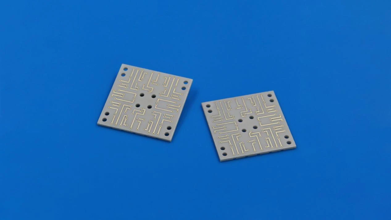
INNOVACERA manufactures high-performance ceramic substrates, including high-purity alumina (96% and 99.6%), aluminum nitride (170 to 230 W/m·K), and silicon nitride (Si₃N₄). We supply bare as-fired substrates, precision lapped/polished plates, and custom metallized ceramics (DPC, DBC, and thick-film circuits) tailored to demanding resistor and power electronic assemblies.
Whether you are evaluating prototypes or qualifying high-volume production substrates, our engineering team can review your power density, dimensions, camber requirements, and metallization layouts.
For technical inquiries and quotation support, please contact sales@innovacera.com.