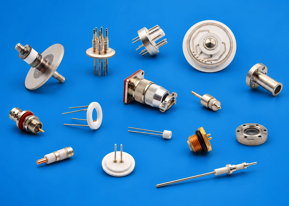
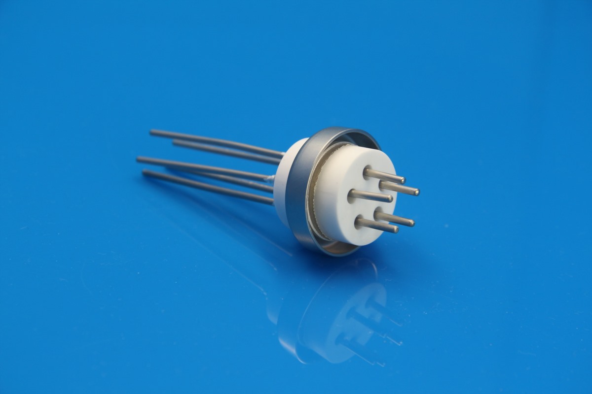
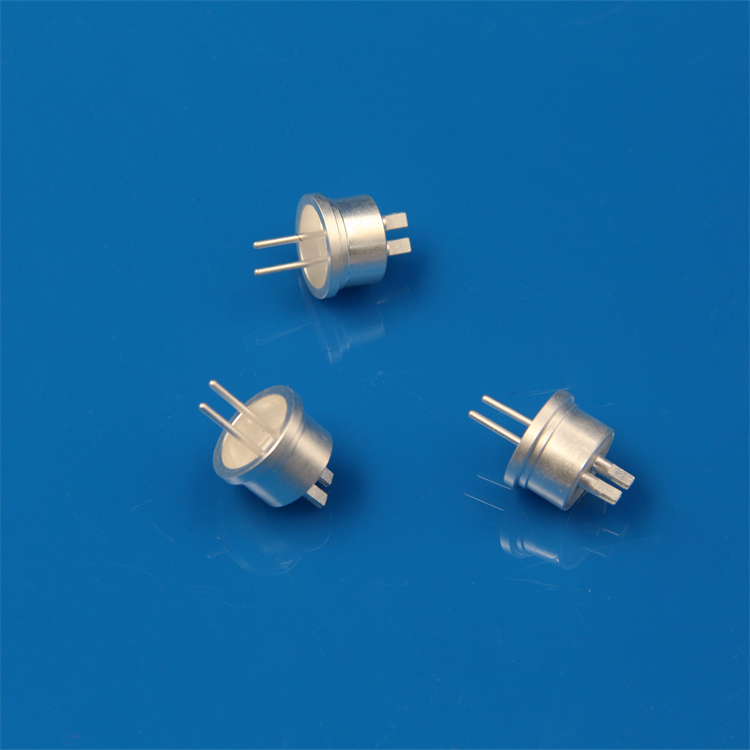
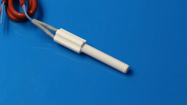
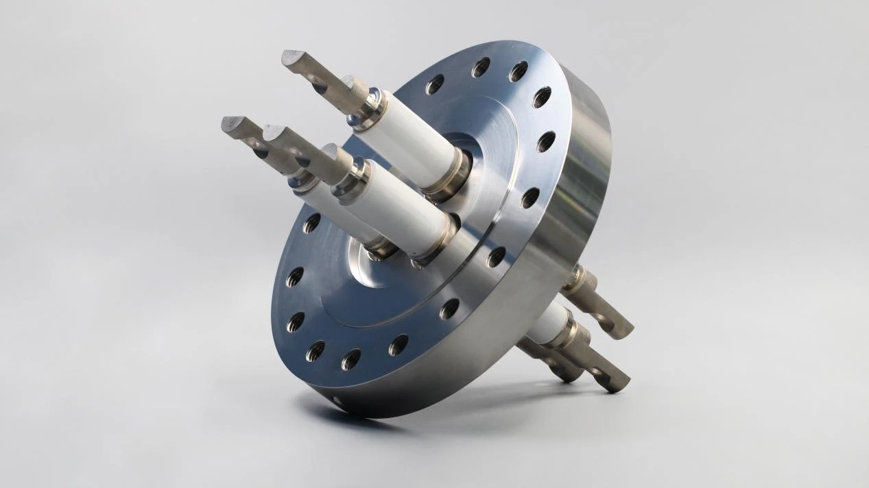
Ceramic-to-metal vacuum feedthroughs pass electrical leads through chamber walls while maintaining a dependable hermetic bond between the ceramic and metal components. In semiconductor, thin-film deposition, and vacuum coating equipment, even a minor leak degrades vacuum integrity, causes batch contamination, and triggers unplanned line stoppages.
A common engineering headache is that feedthroughs often pass initial helium leak tests at room temperature immediately after manufacturing, only to develop catastrophic vacuum leaks after repeated heating and cooling cycles in service. Root cause troubleshooting can be deceptive: the ceramic insulator may appear completely intact, while microscopic leakage paths form along the ceramic-metal interface, the braze alloy boundary, or the flange mating face.
Thermal cycling is a primary trigger, but temperature variation alone does not explain failure. Coefficient of thermal expansion (CTE) mismatches, metallization adhesion quality, braze alloy wetting, structural geometry, and mechanical mounting stress all warrant systematic inspection.
1. What Problems Can Arise from the Difference in Thermal Expansion Between Ceramics and Metals?
Technical ceramics and metals expand and contract at significantly different rates when exposed to temperature swings. Once joined via high-temperature brazing, this thermal expansion mismatch introduces continuous residual shear and tensile stresses at the joint interface.
Under repeated heating and cooling cycles, localized stress concentrations at ceramic edges or joint boundaries can initiate micro-cracks or delamination, permanently compromising hermeticity.
However, joint integrity is not determined solely by the raw CTE values of the two materials. The mechanical ductility of the metal, joint geometry, transition layer thickness, brazing filler selection, and the equipment’s heating/cooling ramp rates all dictate real-world stress levels.
Therefore, when specifying vacuum feedthroughs, electrical insulation and current ratings are insufficient on their own. Engineers must evaluate material compatibility, transition designs, and allowable thermal cycling profiles for the target operating window.
2. What Are the Latent Risks in Brazed Joints and Metallized Interfaces?
Taking high-purity alumina feedthroughs as an example, the ceramic surface must undergo a metallization process (such as Mo-Mn or thick-film metallization followed by Ni plating) prior to brazing. During this sequence, the chemical bonding between the metallized layer and the ceramic substrate, the wetting behavior of the braze alloy, and the furnace atmosphere directly govern joint reliability.
Sub-optimal metallization bonding or incomplete braze alloy coverage leaves sub-micron voids and micro-flaws inside the joint. Such assemblies easily pass factory room-temperature helium leak checks, but repeated thermal expansion and contraction cause these latent flaws to propagate into continuous leak paths. When troubleshooting thermal cycling leaks, inspecting the metallization and brazing interfaces under magnification is just as critical as checking for ceramic body fractures.
3. If a Leak Develops After Thermal Cycling, Where Should the Investigation Start?
When a chamber experiences vacuum loss, follow a structured diagnostic workflow:
Step 1: Isolate the leak source
Confirm whether the leak originates from the ceramic-to-metal feedthrough itself rather than from flange elastomer O-rings, CF knife-edges, or weld seams.
Step 2: Compare initial vs. post-cycling inspection records
If the unit passed factory leak tests but fails after thermal cycling, examine the ceramic-to-metal interface for micro-cracks, braze detachment, or mechanical shear damage resulting from thermal fatigue.
Step 3: Evaluate operational conditions and failure timing
If leakage occurs strictly at elevated temperatures or during dynamic cooling phases, review the heating ramp rate, temperature gradients across the flange, and external mechanical loads exerted on the conductor pins.
Step 4: Combine helium mass spectrometry with non-destructive testing
Helium leak testing quantitatively pinpoints leak locations and rates. Supplementing this with optical microscopy or dye-penetrant inspection helps determine whether the root cause is bulk ceramic cracking, braze dewetting, or metallization peel-off.
Maintenance and quality teams are strongly advised to archive helium leak rates before and after commissioning, alongside temperature ramp logs, dwell cycles, and system vacuum levels. Correlating these data points accelerates root cause identification and prevents recurring field failures.
4. How to Improve the Thermal Cycling Reliability of Ceramic-to-Metal Vacuum Feedthroughs?
Enhancing thermal fatigue resistance requires holistic optimization across material matching, joint mechanics, and process control:
- CTE-Matched Material Pairing: Select controlled-expansion alloys (such as Kovar, 42Ni-Fe, or OFHC copper with stress-relief geometry) paired with high-strength alumina or specialized ceramic formulations matched to the service temperature.
- Stress-Relieving Structural Design: Optimize ceramic wall thickness, conductor pin diameters, transition sleeve geometries, and braze meniscus contours to eliminate sharp stress risers at seal boundaries.
- Precision Metallization & Brazing Control: Strictly govern metallizing layer thickness, sintering atmosphere dew point, nickel plating adhesion, and vacuum brazing thermal curves to guarantee complete wetting and void-free braze fillets.
- Rigorous Thermal Cycle Qualification: For critical vacuum applications, routine factory testing should go beyond ambient leak checks. Subjecting validation samples to repeated thermal cycling profiles followed by high-sensitivity helium mass spectrometer testing ensures field durability under production conditions.
INNOVACERA Custom Ceramic-to-Metal Vacuum Feedthrough Solutions
INNOVACERA engineers and manufactures high-reliability ceramic-to-metal assemblies and vacuum electrical feedthroughs tailored to demanding industrial, analytical, and semiconductor environments. We support custom designs spanning single-pin to multi-pin configurations, high-voltage isolators, high-current coaxial feedthroughs, and custom-flanged hermetic assemblies.
To ensure long-term thermal cycling performance, our team reviews operating temperature ranges, target vacuum thresholds, thermal ramp rates, conductor current loads, and flange integration requirements directly from your drawings.
For technical inquiries or custom feedthrough development, contact our engineering sales team at sales@innovacera.com.