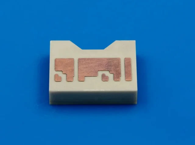
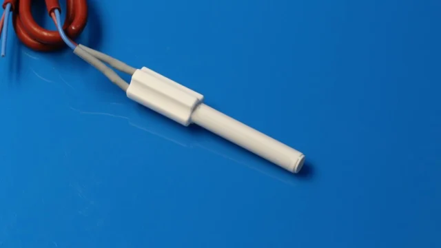
When engineers evaluate an AlN vs. alumina laser ceramic submount for diode packaging, AlN’s much higher thermal conductivity makes it seem like the obvious choice. In many high-power packages, that is true. But it is not the whole trueth.
The real question is how much of the temperature rise from the laser junction to the package base occurs across the ceramic. For a high-power CW laser in a compact package, AlN often justifies its higher cost. For a moderate-power device with an efficient package base and enough thermal margin, alumina may work equally well in practice.
At INNOVACERA, we prefer to look at the complete package before recommending either material.
Why the Submount Matters
Heat generated at the laser junction follows a short but complex path:
Laser junction → laser die → die attach → ceramic submount → TEC or package base → heat sink
The submount sits directly below the laser die, so it has to do several jobs at once. It supports the die, provides electrical insulation and spreads heat into the larger package structure. Its surface must also be suitable for the customer’s metallization, die-attach and wire-bonding processes.
This becomes more demanding as laser packages become smaller. High-power CW DFB lasers used in optical communication are a good example. They must maintain stable output and wavelength while operating continuously within a limited footprint. Even when the TEC temperature is well controlled, the laser junction can run considerably hotter if heat is restricted by the die attach or submount.
How AlN and Alumina Compare
| Property | AlN | 96% Alumina |
|---|---|---|
| Thermal conductivity | 170–230 W/m·K | Approximately 24 W/m·K |
| Coefficient of thermal expansion | Approximately 4–6 × 10⁻⁶/K | Approximately 7.2 × 10⁻⁶/K |
| Volume resistivity | Above 10¹⁴ Ω·cm | Approximately 10¹⁴ Ω·cm |
| Dielectric strength | Typically above 15 kV/mm | Approximately 15 kV/mm |
| Relative material cost | Higher | Lower |
Both materials provide reliable electrical insulation. The main difference is their ability to move heat.
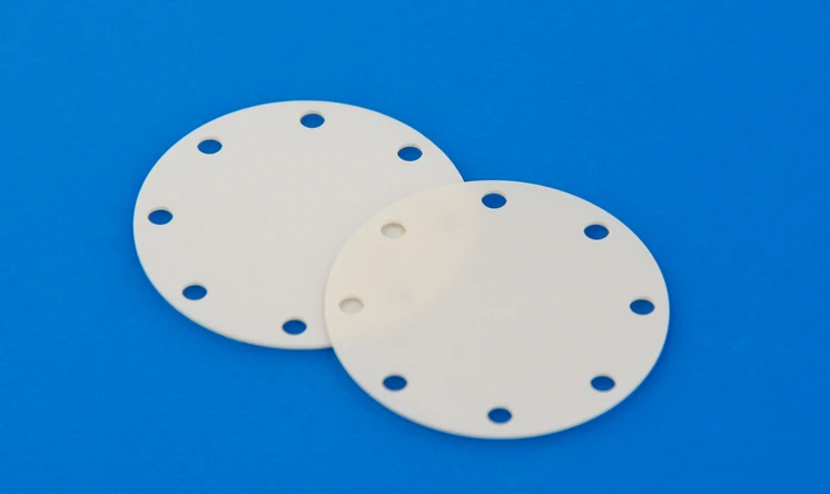
For a ceramic layer, thermal resistance is approximately:
Rth=t/kA
Here, (t) is the ceramic thickness, (k) is thermal conductivity and (A) is the effective heat-transfer area.
If the dimensions are identical, an AlN layer has roughly one-seventh to one-tenth of the thermal resistance of 96% alumina. The total package improvement will be smaller because the die attach and other interfaces also contribute thermal resistance, but the difference is still significant in a thermally constrained design.
Where AlN Makes a Real Difference
AlN is normally the better choice when a laser operates continuously at high power and heat must pass through a small area. In this situation, the ceramic can become a meaningful part of the junction-to-base thermal resistance. Replacing alumina with AlN allows heat to reach the TEC or package base more efficiently.
This is particularly useful in compact DFB laser packages, where the design cannot simply add a larger heat spreader. AlN also helps in assemblies that place the laser, driver or other active devices close together. Better lateral heat spreading reduces local hot spots and limits thermal interaction between nearby components.
Wavelength-sensitive packages may also benefit. A TEC controls the temperature at its own surface, not directly at the laser junction. Lower thermal resistance between the junction and TEC reduces the temperature difference between them, making the controlled package temperature more representative of the laser’s actual operating condition.
AlN has another useful property: its coefficient of thermal expansion is generally closer to that of common semiconductor materials than alumina. This can reduce stress in the die-attach structure during assembly and temperature cycling. The actual benefit depends on the die material, solder system, joining temperature and component size, so CTE should always be considered as part of the complete assembly.
Where Alumina Still Makes Sense
Alumina remains a sound engineering choice for many laser packages. It is electrically insulating, mechanically stable, widely available and more economical than AlN.
If the laser produces a moderate amount of heat and the package already includes an effective metal base, the ceramic may not be the main thermal bottleneck. In that case, changing to AlN may add cost without producing a meaningful reduction in junction temperature.
Alumina is also attractive for volume production when thermal testing confirms enough operating margin. There is little value in specifying a higher-performance ceramic if the existing package already meets its temperature and reliability targets.
Thickness matters as well. A thinner alumina submount has lower through-thickness thermal resistance and may be suitable for some designs. However, reducing thickness can affect flatness, stiffness, handling yield and resistance to cracking. The sensible comparison is therefore between two actual designs—such as thin alumina and standard-thickness AlN—not simply between their bulk conductivity values.
The Interfaces Can Matter as Much as the Ceramic
A good AlN submount will not correct a poor assembly process.
Voids or uneven thickness in the die-attach layer can create local hot spots directly beneath the laser. Poor submount flatness may lead to inconsistent bonding or reduced contact with the package base. A thick joining layer between the submount and TEC can add enough resistance to offset part of the benefit gained from using AlN.
Surface finish also needs to match the downstream process. A polished surface may be required for one metallization system, while another process depends on a different roughness range for reliable adhesion. The drawing should therefore define flatness, parallelism and surface roughness according to the actual assembly method rather than using unnecessarily tight values.
This is why we do not judge a laser submount from thermal conductivity alone. The ceramic grade, thickness, surface condition and joining process all influence the finished package.
A Practical Selection Guide
| Package Condition | Suggested Starting Point |
|---|---|
| High-power CW DFB laser | AlN |
| Compact package with high heat flux | AlN |
| Strict junction-temperature or wavelength control | AlN |
| Several heat-generating devices on one submount | AlN |
| Moderate-power laser with sufficient thermal margin | Alumina |
| Large package with an effective metal heat spreader | Evaluate both |
| Cost-sensitive volume production | Alumina, after thermal verification |
| Thermal margin is uncertain | Model and prototype both materials |
What We Need to Review a Submount
For an initial material review, the most useful information is:
- Laser type and CW or pulsed operation
- Estimated heat dissipation
- Submount dimensions and thickness
- Maximum allowable temperature
- Flatness and surface-roughness requirements
- Die-attach and downstream metallization process
- Prototype and annual quantities
Electrical input alone does not show the complete heat load. Optical output and laser efficiency are also needed to estimate how much power becomes heat inside the package.
Which Material Should You Choose?
For a high-power CW laser in a compact package, AlN is usually the better starting point. Its higher thermal conductivity provides more margin for controlling junction temperature, wavelength stability and long-term performance.
For a moderate-power device with an efficient package structure, alumina may meet the same functional requirements at a lower cost.
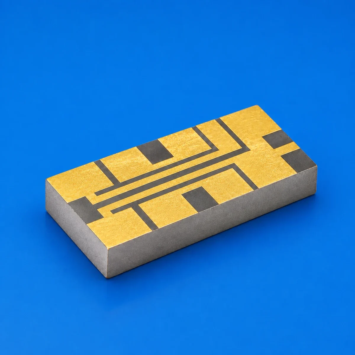
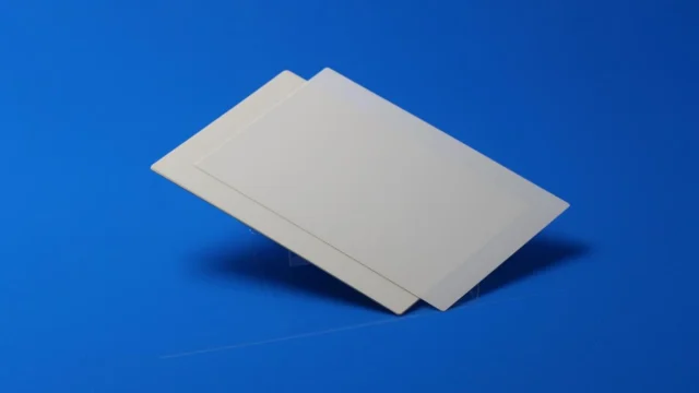
INNOVACERA supplies AlN and alumina bare ceramic substrates with customized dimensions, thicknesses and surface conditions. By reviewing the package layout and operating requirements, we can help determine whether AlN will provide a useful thermal advantage or whether alumina is already sufficient for the design.
The values shown are representative material properties. Final specifications depend on ceramic grade, geometry, processing method and inspection requirements.