
Dear All Partners,INNOVACERA wish you and your family members Happy New Year 2020.Sincerely May Peace, Happiness and Good Fortune be with you and your family members always!Many thanks for your long s…
Dear All Partners,INNOVACERA wish you and your family members Happy New Year 2020.Sincerely May Peace, Happiness and Good Fortune be with you and your family members always!Many thanks for your long s…

Dear Partners,Merry Christmas and Happy New Year ❤️ 🎄❤️Best Wishes to you and your family. 💏👭💕The INNOVACERA team
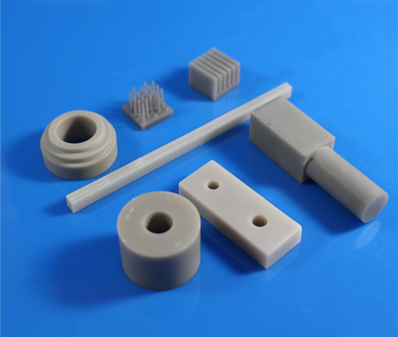
Aluminium nitride has become an important precision ceramic material because of its high thermal conductivity, high insulation resistance coefficient, excellent mechanical strength, and thermal shock …
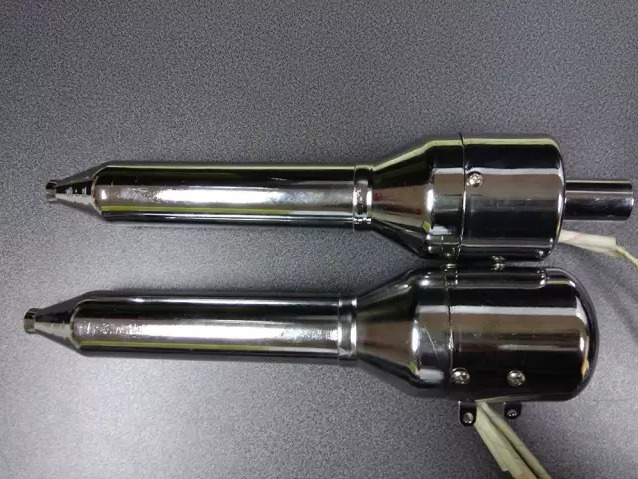
Classification of hot air guns: hot air gun with built-in fan; air gun without the fan.The drypoint can reach 1200 ° C.Using high-performance silicon nitride ceramics as the substrate, high-temperatur…
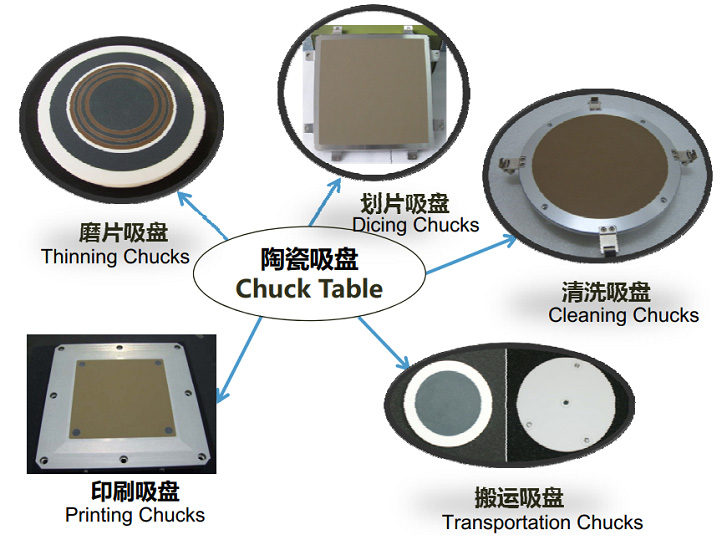
The ceramic chuck table is applied to the fields of silicon wafer, semiconductor compound wafer, piezoelectric ceramic, glass, LED, semiconductor package component substrate, optical component thinnin…
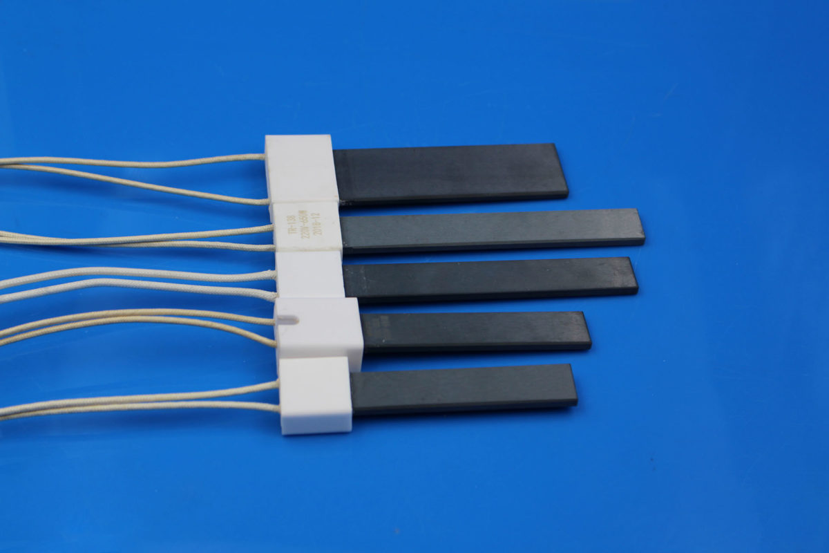
Silicon nitride ceramic heating element is based on high-performance silicon nitride ceramics, high temperature and high mechanical strength, thermal shock resistance is strong, resistance to acid and…
INNOVACERA® ceramic laser reflectors are high-efficiency diffuse reflectors. The perfect diffuse reflection and high reflection efficiency are effectively exploited in laser systems in the 500 nm to 1…
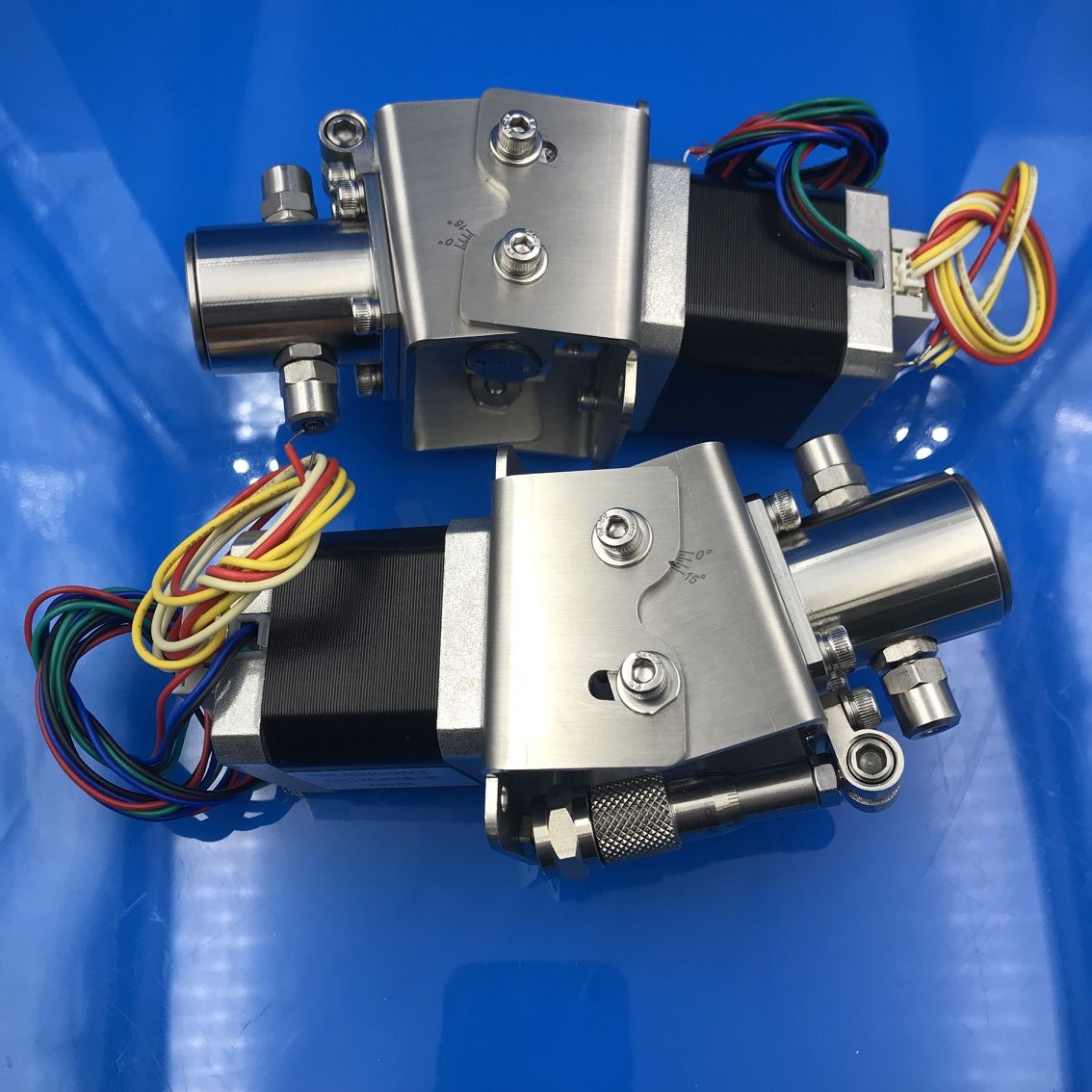
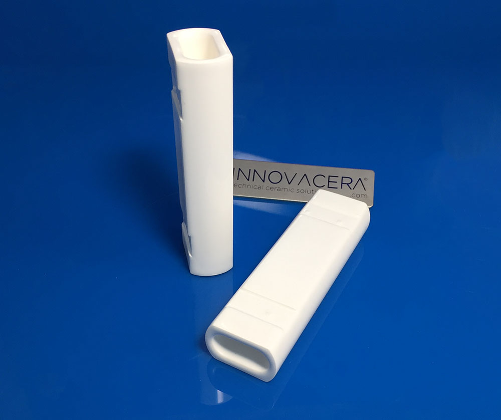
Disassembling and Cleaning the Ceramic Valveless Piston Pump Step:1. Rotate the pump shaft and stop turning when you see the circle on the pump shaft.2. Remove the four screws from the piston head and…
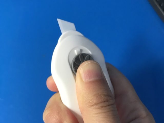
Innovacera manufactures all kind of cutters for special applications like cutting plastic, capsules, packaging, rubber, fibre, film, foil, mat board as well as other products.The design can be accordi…
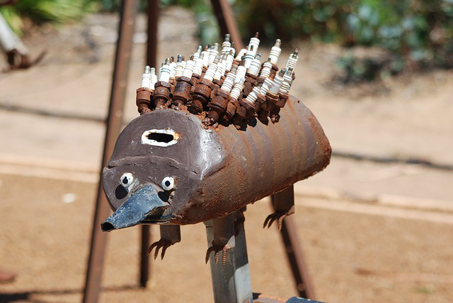
Spark plugs are an integral part of the motorization era. Everyone travels every day, and there are countless small spark plugs that support this vast modern society. Today, I will tell you about the …